UTICA BOILERS JE Installation Manual
Browse online or download Installation Manual for Unknown UTICA BOILERS JE. Utica Boilers JE Operation and Installation Manual User Manual
- Page / 16
- Table of contents
- BOOKMARKS
Summary of Contents
INSTALLATION AND OPERATING INSTRUCTIONS CSD-1 COMMERCIAL BOILER CONTROLS P/N 240010413, Rev. A [12/2013]SUPPLEMENTAL
ALARMCONTACTSJUMPERUT 1145-2BOILERSTATCOM24 VACRPILOT SAFETY SHUTOFFVALVEBLACKBLACKWHITEBLUED DMAIN GAS VALVEROBERT SHAW 7000 DE RHCTR THSPARK CABLETO
ELECTRICAL WIRE DIAGRAMS - CSD-1 STEAM BOILERSWITH CONDENSATE PUMP/GRAVITY RETURN11
3ELECTRICAL WIRE DIAGRAMS - CSD-1 STEAM BOILERSWITH CONDENSATE PUMP/GRAVITY RETURN12
ELECTRICAL WIRE DIAGRAMS - CSD-1 STEAM BOILERSWITH BOILER FEED PUMP RETURN13
ELECTRICAL WIRE DIAGRAMS - CSD-1 STEAM BOILERSWITH BOILER FEED PUMP RETURN314
NOTES15
Your commercial boiler is furnished with combustion side water or steam controls to meet our interpretation of the American Society of Mechanical Engi
Table #1: CSD-1 Complete Boiler Material ListModelSectionsCSD-1 Component Carton a & bSteam Trim CartondCSD-1 AC CartonJacket End Panel CartonBase
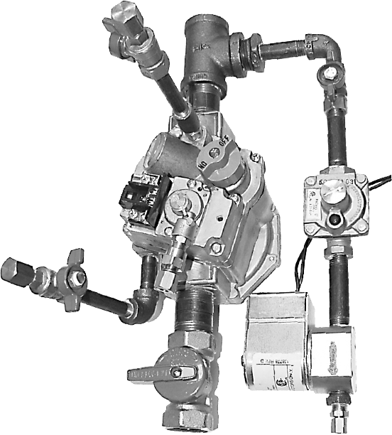
Table #3: CSD-1 Electronic Ignition Base Material ListItem Description Part No. Qty.1 ¾” 90 Street Elbow Back 14693040 12 ¾” Manual Shutoff Valve 146
WATER LEVEL 29” TO FLOORSteam Side Control - Two low water cutoff devices and two pressuretrols, one with auto reset and the second with manual reset,
Boiler feed pump return additional parts See Table #5b. See Figure #2 for installed locations of additional parts.•Tappings B & B - Water gauge g
Call For HeatControl recognizes call for heat when power is applied to 24V terminal on control module. Since control receives signal from the thermost
Gas Valve SensingIf either or both the pilot and main gas valves are sensed to be on when commanded to be off, or if no voltage appears at gas valve o
The suggested schematic wiring diagrams are included. Please use the appropriate one for the installation.CSD-1 HONEYWELL VR8304M,H MAIN GAS VALVE CON
Related products and manuals for Unknown UTICA BOILERS JE
 (28 pages)
(2 pages)
(1 pages)
(24 pages)
(28 pages)
(2 pages)
(1 pages)
(24 pages)
 (16 pages)
(1 pages)
(16 pages)
(1 pages)
© 2020, manymanuals.com. All rights reserved. | 0.238 s |
 Manymanuals.com
 Manymanuals.de
 Manymanuals.fr
 Manymanuals.it
 Manymanuals.pl
 Manymanuals.cz
 Manymanuals.es
 Manymanuals-pt.com
Comments to this Manuals